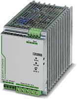
QUINT-PS/3AC - Alimentatore per Guida DIN Trifase
Robusto con tecnologia SFB (Selective Fuse Breaking) ed NFC
- Tensioni di uscita: 24 o 48 V DC
- Gamme Tensioni di Uscita Regolabili: 18 a 56 V DC
- Corrente di uscita: 10, 20 o 40 A
- Potenza di uscita: 240, 480 o 960 W
- Funziona con gamme di tensioni di ingresso AC o DC trifase o bifase
Gli Alimentatori Trifase QUINT offrono una gamma di robusti convertitori AC/DC e DC/DC costruiti per soddisfare le aspettative di alta stabilità ed efficienza degli ambienti di controllo industriali, di automazione macchine e controllo di processo. Possiedono anche una combinazione unica di monitoraggio funzionale preventivo e riserva di potenza, in una dimensione incredibilmente compatta. Perfetti per l'uso in applicazioni ad alta potenza, questi alimentatori a commutazione (in modalità commutata) garantiscono una tensione di uscita costante anche in caso di oscillazioni della tensione sulla rete di alimentazione. Durante il funzionamento in parallelo e quando connessi a fasi diverse, i carichi vengono alimentati anche in caso di problemi con la tensione di ingresso. Dotati di tutte le certificazioni di sicurezza richieste per supportare apparecchiature ITE (Information Technology Equipment), un involucro robusto, temperature di esercizio estese, capacità di carico di picco elevate e alte tensioni di isolamento, gli alimentatori industriali QUINT sono concepiti per soddisfare le esigenze di svariate applicazioni industriali.
SOVRALIMENTAZIONE: avvio di carichi difficili in modo affidabile
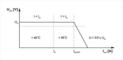
Per configurare, ottimizzare ed espandere grandi sistemi è richiesto un elevato livello di flessibilità. Per adattare in modo ottimale un sistema o una macchina ai propri requisiti, è fondamentale avere una riserva di potenza nell'unità di alimentazione. L'alimentatore QUINT eroga fino al 50% di corrente in più senza caduta di tensione. Risulta utile quando non è possibile prevedere quali carichi saranno attivati contemporaneamente o se le alte correnti di inserzione dei carichi capacitivi devono essere assorbite senza cali di tensione. Risulta utile quando non è possibile prevedere quali carichi saranno attivati contemporaneamente o se le alte correnti di inserzione dei carichi capacitivi devono essere assorbite senza cali di tensione. Con la funzione di sovralimentazione QUINT, una sovralimentazione statica eroga costantemente fino al 125% della corrente nominale. Inoltre, è possibile sfruttare la sovralimentazione dinamica per alimentare fino al 200% della corrente nominale per 5 secondi, durante l'avviamento di carichi pesanti.
Il monitoraggio funzionale preventivo segnala condizioni di funzionamento critiche prima che si verifichino
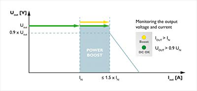
Con un alimentatore industriale QUINT, tensione di uscita e corrente di uscita sono costantemente monitorate. Il monitoraggio funzionale preventivo visualizza le condizioni operative critiche e le indica in locale e in remoto al controller, secondo le seguenti modalità:
- Tramite LED
- Tramite contatto di relè flottante
- Tramite uscita di commutazione attiva
Temperatura di esercizio industriale da -25°C a +70°C
Le apparecchiature che si trovano nei dispositivi di gestione del traffico, nelle tubazioni di trasporto petrolio e gas, di tracciamento meteorologico, in applicazioni industriali e in ambienti esterni devono funzionare a temperature non supportate dagli alimentatori disponibili in commercio. Con una temperatura di esercizio tra -25°C e +70°C e un avviamento affidabile del dispositivo a -40°C, l' alimentatore industriale QUINT è l'ideale per l'uso con apparecchiature in ambienti difficili e soggette a temperature estreme.
Alta efficienza e basso consumo di potenza senza carico
Rispetto agli altri prodotti sul mercato, l'alimentatore industriale QUINT offre eccellenti risparmi energetici. Con un consumo energetico senza carico ridotto e alta efficienza a carico nominale, solo una piccola quantità di energia elettrica viene convertita in energia termica indesiderata, rendendo questi alimentatori estremamente ecologici.
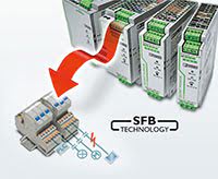
Tecnologia SFB (Selective Fuse Breaking, interruzione selettiva a fusibile)
La tecnologia SFB può essere adottata per far scattare in modo rapido e affidabile interruttori disgiuntori miniaturizzati e i fusibili collegati sul secondario. In caso di cortocircuito sul secondario, l'alimentatore QUINT eroga fino a 6 volte la corrente nominale per 15 ms. I percorsi di corrente difettosi vengono disattivati selettivamente, il guasto localizzato e i componenti importanti del sistema rimangono in funzione. I carichi collegati in parallelo continuano a essere alimentati con energia, garantendone il funzionamento costante.
- Scatto degli interruttori disgiuntori: l'interruttore disgiuntore tipicamente viene fatto scattare dall'elevata corrente SFB entro 3-5 ms. Di conseguenza, ogni caduta di tensione per i carichi collegati in parallelo viene evitata.
- Scatto di un fusibile: i fusibili vengono fatti scattare fondendo il punto di rottura prestabilito all'interno della capsula del fusibile. La caratteristica di scatto del fusibile è descritta dall'integrale della fusione (I²t). Per ottenere un tempo di scatto molto breve, è fondamentale avere una corrente elevata.
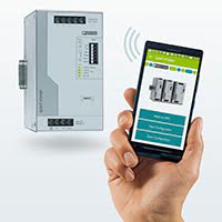
Near Field Communication (NFC)
Near Field Communication (NFC) è uno standard di trasmissione per lo scambio di dati senza fili e senza contatti a distanze ravvicinate. Grazie alla tecnologia NFC, è possibile parametrizzare facilmente le impostazioni dell'alimentatore QUINT come ad esempio la definizione delle soglie di segnale per il monitoraggio funzionale preventivo, la regolazione della tensione in uscita e l'adattamento della curva caratteristica di uscita agli specifici requisiti utilizzando un PC, un cellulare o un dispositivo terminale mobile. Dal dispositivo terminale mobile si possono anche salvare e inviare profili di configurazione. QUINT Power NFC App sul Google Play Store.
Ambienti di applicazione ideali per un alimentatore trifase QUINT
- motori di comando e altri dispositivi
- costruzione di macchine
- processo di produzione automatizzato
- apparecchiature di controllo industriale, automazione, assemblaggio e test
- controllo, sicurezza e sorveglianza di edifici e sistemi di controllo del clima.
- alimenta innumerevoli dispositivi di automazione industriali, quali sensori, controller e valvole
Altri motivi per cui scegliere l'alimentatore industriale trifase QUINT
- L'ingresso più resistente: elevata immunità ai disturbi, scaricatore a gas integrato (fino a 6 kV) e ad un tempo di copertura delle interruzioni di rete ≥ 20 ms
- Il design allungato e sottile permette di risparmiare spazio nella scatola di comando
- Ingresso/Uscita isolamento di tensione: 4 kV AC
- Protezioni: da cortocircuito, sovraccarico, sovratensione, temperatura eccessiva
- Valori MTBF (Mean Time Between Failure, tempo medio tra i guasti) elevati
Specifications
HTSUS Number:
QUINT-PS/3AC/48DC/20: 8504.40.7018, QUINT-PS/3AC/24DC/40: 8504.40.7018, QUINT4-PS/3AC/24DC/10: 8504.40.7012, QUINT4-PS/3AC/24DC/20: 8504.40.7012
UNSPSC Code:
39121004
ECCN:
EAR99

Environmental Product Compliance
REACH SVHC
23208278
Lead 7439-92-1
28668028
Lead 7439-92-1
29046218
Lead 7439-92-1
29046228
Lead 7439-92-1
China RoHS
Environmentally Friendly Use Period = 25;
General
Net weight
23208278
2.5 kg
28668028
2.5 kg
29046218
0.9 kg
29046228
1.1 kg
Efficiency
23208278
> 93 % (at 400 V AC and nominal values)
28668028
> 94 % (at 400 V AC and nominal values)
29046218
typ. 93 % (400 V AC)
29046228
typ. 93.9 % (400 V AC)
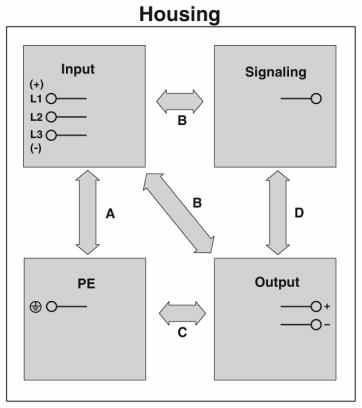
Insulation voltage input/output
23208278
- 4 kV AC (type test)
- 2 kV AC (routine test)
28668028
- 4 kV AC (type test)
- 2 kV AC (routine test)
29046218
- 4 kV AC (type test)
- 2.4 kV AC (routine test)
29046228
- 4 kV AC (type test)
- 2.4 kV AC (routine test)
Insulation voltage input / PE
23208278
- 3.5 kV AC (type test)
- 2 kV AC (routine test)
28668028
- 3.5 kV AC (type test)
- 2 kV AC (routine test)
29046218
- 3.5 kV AC (type test)
- 2.4 kV AC (routine test)
29046228
- 3.5 kV AC (type test)
- 2.4 kV AC (routine test)
Insulation voltage output / PE
23208278
500 V DC (routine test)
28668028
500 V DC (routine test)
29046218
0.5 kV DC (type test)
29046228
0.5 kV DC (type test)
Protection class
I
Degree of protection
IP20
MTBF (IEC 61709, SN 29500)
23208278
889679,72 h (25°C)
501504,51 h (40°C)
216825,67 h (60°C)
28668028
> 880000 h (25°C)
> 500000 h (40°C)
> 216000 h (60°C)
29046218
> 1034000 h (25°C)
> 654000 h (40°C)
> 320000 h (60°C)
29046228
> 985000 h (25°C)
> 638000 h (40°C)
> 311000 h (60°C)
Mounting position
horizontal DIN rail NS 35, EN 60715
Assembly instructions
alignable: PN ≥50%,
5 mm horizontally
15 mm next to active components
50 mm vertically alignable: PN <50%
0 mm horizontally
40 mm vertically top
20 mm vertically bottom
Operating voltage display
23208278
28668028
Green LED
29046218
29046228
Efficiency
23208278
28668028
29046218
typ. 92.6 % (480 V AC)
29046228
typ. 93.8 % (480 V AC)
Insulation voltage output / PE
23208278
28668028
29046218
0.5 kV DC (routine test)
29046228
0.5 kV DC (routine test)
Standards and Regulations
Electromagnetic compatibility
Conformance with EMC Directive 2014/30/EU
Noise immunity
23208278
EN 61000-6-2:2005
28668028
EN 61000-6-2:2005
29046218
Immunity according to EN 61000-6-1 (residential), EN 61000-6-2 (industrial), and EN 61000-6-5 (power station equipment zone), IEC/EN 61850-3 (energy supply)
29046228
Immunity according to EN 61000-6-1 (residential), EN 61000-6-2 (industrial), and EN 61000-6-5 (power station equipment zone), IEC/EN 61850-3 (energy supply)
Connection in acc. with standard
23208278
CSA
28668028
CSA
29046218
29046228
Standards/regulations
EN 61000-4-2
Contact discharge
4 kV (Test Level 2)
Standards/regulations
EN 61000-4-3
Frequency range
80 MHz ... 1 GHz
Test field strength
10 V/m (Test Level 3)
Frequency range
1.4 GHz ... 2 GHz
Test field strength
3 V/m (Test Level 2)
Standards/regulations
EN 61000-4-4
Comments
Criterion B
Standards/regulations
23208278
EN 61000-4-6
28668028
EN 61000-6-3
29046218
EN 61000-4-6
29046228
EN 61000-4-6
Frequency range
0.15 MHz ... 80 MHz
Voltage
10 V (Test Level 3)
Low Voltage Directive
23208278
Conformance with LV directive 2006/95/EC
28668028
Conformance with LV directive 2006/95/EC
29046218
Conformance with Low Voltage Directive 2014/35/EC
29046228
Conformance with Low Voltage Directive 2014/35/EC
Standard - Safety of transformers
23208278
IEC 61558-2-17
28668028
29046218
EN 61558-2-16 (air clearances and creepage distances only)
29046228
EN 61558-2-16 (air clearances and creepage distances only)
Standard - Electrical safety
IEC 60950-1/VDE 0805 (SELV)
Standard – Electronic equipment for use in electrical power installations and their assembly into electrical power installations
23208278
EN 50178/VDE 0160 (PELV)
28668028
EN 50178/VDE 0160 (PELV) / Overvoltage category III
29046218
EN 50178/VDE 0160 (PELV)
29046228
EN 50178/VDE 0160 (PELV)
Standard - Safe isolation
DIN VDE 0100-410
Standard – Protection against shock currents, basic requirements for protective separation in electrical equipment
23208278
EN 50178
28668028
29046218
29046228
Standard – Limitation of mains harmonic currents
EN 61000-3-2
Standard - Equipment safety
23208278
BG (design tested)
28668028
GS (tested safety)
29046218
29046228
Standard - Approval for medical use
23208278
IEC 60601-1, 2 x MOOP
28668028
29046218
29046228
UL approvals
23208278
- UL/C-UL listed UL 508
- UL/C-UL Recognized UL 60950-1 (3-wire + PE, star net)
- UL ANSI/ISA-12.12.01 Class I, Division 2, Groups A, B, C, D (Hazardous Location)
28668028
- UL/C-UL listed UL 508
- UL/C-UL Recognized UL 60950-1 (3-wire + PE, star net)
- UL ANSI/ISA-12.12.01 Class I, Division 2, Groups A, B, C, D (Hazardous Location)
29046218
- UL/C-UL listed UL 508
- UL/C-UL Recognized UL 60950-1
- UL ANSI/ISA-12.12.01 Class I, Division 2, Groups A, B, C, D (Hazardous Location)
29046228
- UL/C-UL listed UL 508
- UL/C-UL Recognized UL 60950-1
- UL ANSI/ISA-12.12.01 Class I, Division 2, Groups A, B, C, D (Hazardous Location)
Shock
18 ms, 30g, in each space direction (according to IEC 60068-2-27)
Vibration (operation)
23208278
< 15 Hz, amplitude ±2.5 mm (according to IEC 60068-2-6)
15 Hz ... 150 Hz, 2.3g, 90 min.
28668028
5 Hz ... 100 Hz resonance search 2.3g, 90 min., resonance frequency 2.3g, 90 min. (according to DNV GL Class C)
29046218
5 Hz ... 100 Hz resonance search 2.3g, 90 min., resonance frequency 2.3g, 90 min. (according to DNV GL Class C)
29046228
5 Hz ... 100 Hz resonance search 2.3g, 90 min., resonance frequency 2.3g, 90 min. (according to DNV GL Class C)
Information technology equipment - safety (CB scheme)
23208278
CB Scheme
28668028
CB Scheme
29046218
29046228
Rail applications
23208278
EN 50121-4
28668028
EN 50121-4
29046218
EN 50121-3-2
29046228
EN 50121-3-2
Overvoltage category (EN 62477-1)
23208278
III
28668028
III
29046218
III (≤ 2000 m)
29046228
III (≤ 2000 m)
Standards/regulations
23208278
28668028
EN 61000-4-6
29046218
EN 61000-4-8
29046228
EN 61000-4-8
Standard - Safe isolation
23208278
28668028
DIN VDE 0106-101
29046218
29046228
Shipbuilding approval
23208278
28668028
DNV GL (EMC A), ABS, LR, RINA, NK, BV
29046218
DNV GL, PRS, BV, LR, ABS
29046228
DNV GL, PRS, BV, LR, ABS
Noise emission
23208278
28668028
29046218
Additional basic standard EN 61000-6-5 (immunity in power station), IEC/EN 61850-3 (energy supply)
29046228
Additional basic standard EN 61000-6-5 (immunity in power station), IEC/EN 61850-3 (energy supply)
Conducted noise emission
23208278
28668028
29046218
EN 55016 EN 61000-6-4 (Class A)
29046228
EN 55016 EN 61000-6-4 (Class A)
Standards/regulations
23208278
28668028
29046218
- EN 61000-4-11
- EN 61000-4-9
- EN 61000-4-12
- EN 61000-4-16
- EN 61000-4-18
29046228
- EN 61000-4-11
- EN 61000-4-9
- EN 61000-4-12
- EN 61000-4-16
- EN 61000-4-18
Standard - power supply devices for low voltage with DC output
23208278
28668028
29046218
EN 61204-3
29046228
EN 61204-3
EMC requirements, power plant
23208278
28668028
29046218
- IEC 61850-3
- EN 61000-6-5
29046228
Approval - requirement of the semiconductor industry with regard to mains voltage dips
23208278
28668028
29046218
SEMI F47-0706; EN 61000-4-11
29046228
SEMI F47-0706; EN 61000-4-11
Overvoltage category (EN 60950-1)
23208278
28668028
29046218
II (≤ 5000 m)
29046228
II (≤ 5000 m)
Overvoltage category (EN 61010-1)
23208278
28668028
29046218
II (≤ 5000 m)
29046228
II (≤ 5000 m)
Connection data, input
Connection method
Screw connection
Conductor cross section solid min.
0.2 mm²
Conductor cross section solid max.
6 mm²
Conductor cross section flexible min.
0.2 mm²
Conductor cross section flexible max.
4 mm²
Conductor cross section AWG min.
23208278
18
28668028
18
29046218
30
29046228
30
Conductor cross section AWG max.
10
Stripping length
23208278
7 mm
28668028
7 mm
29046218
8 mm
29046228
8 mm
Screw thread
23208278
M4
28668028
M3
29046218
29046228
Output data
Nominal output voltage
23208278
48 V DC ±1 %
28668028
24 V DC ±1 %
29046218
24 V DC
29046228
24 V DC
Setting range of the output voltage (USet)
23208278
30 V DC ... 56 V DC (> 48 V DC, constant capacity restricted)
28668028
18 V DC ... 29.5 V DC (> 24 V DC, constant capacity restricted)
29046218
24 V DC ... 29.5 V DC (constant capacity)
29046228
24 V DC ... 29.5 V DC (constant capacity)
Nominal output current (IN)
23208278
20 A (-25°C ... 60°C, UOUT = 48 V DC)
28668028
40 A (-25°C ... 60°C, UOUT = 24 V DC)
29046218
10 A
29046228
20 A
POWER BOOST (IBoost)
23208278
22.5 A (-25°C ... 40°C permanent, UOUT = 48 V DC)
28668028
45 A (-25°C ... 40°C permanent, UOUT = 24 V DC)
29046218
29046228
Selective Fuse Breaking (ISFB)
23208278
100 A (12 ms)
28668028
215 A (12 ms)
29046218
60 A (15 ms)
29046228
120 A (15 ms)
Derating
23208278
60°C ... 70°C (2.5%/K)
28668028
60°C ... 70°C (2.5%/K)
29046218
> 60°C (2.5%/K)
29046228
> 60°C (2.5%/K)
Connection in parallel
Yes, for redundancy and increased capacity
Connection in series
Yes
Feedback resistance
23208278
max. 60 V DC
28668028
max. 35 V DC
29046218
≤ 35 V DC
29046228
≤ 35 V DC
Protection against surge voltage on the output
23208278
< 60 V DC
28668028
< 35 V DC
29046218
≤ 32 V DC
29046228
≤ 32 V DC
Active current limitation
23208278
Approx. IBOOST = 22.5 A (for short-circuit)
28668028
29046218
29046228
Control deviation
23208278
- < 1 % (change in load, static 10 % ... 90 %)
- < 4 % (change in load, dynamic 10 % ... 90 %)
- < 0.1 % (change in input voltage ±10 %)
28668028
- < 1 % (change in load, static 10 % ... 90 %)
- < 3 % (change in load, dynamic 10 % ... 90 %)
- < 0.1 % (change in input voltage ±10 %)
29046218
- < 0.5 % (Static load change 10 % ... 90 %)
- < 2 % (Dynamic load change 10 % ... 90 %, (10 Hz))
- < 0.25 % (change in input voltage ±10 %)
29046228
- < 0.5 % (Static load change 10 % ... 90 %)
- < 3 % (Dynamic load change 10 % ... 90 %, (10 Hz))
- < 0.25 % (change in input voltage ±10 %)
Residual ripple
23208278
< 50 mVPP (with nominal values)
28668028
< 40 mVPP (with nominal values)
29046218
< 75 mVPP (with nominal values)
29046228
< 60 mVPP (with nominal values)
Output power
23208278
960 W
28668028
960 W
29046218
240 W
29046228
480 W
Typical response time
23208278
< 1 s
28668028
< 0.5 s
29046218
300 ms (from SLEEP MODE)
29046228
300 ms (from SLEEP MODE)
Maximum power dissipation in no-load condition
23208278
24 W
28668028
18 W
29046218
< 5 W (400 V AC)
29046228
< 7 W (400 V AC)
Power loss nominal load max.
23208278
70 W
28668028
63 W
29046218
< 19 W (400 V AC)
29046228
< 32 W (400 V AC)
Peak switching voltages nominal load
23208278
28668028
< 5 mVPP (at nominal values, 20 MHz)
29046218
29046228
Static Boost (IStat.Boost)
23208278
28668028
29046218
12.5 A
29046228
25 A
Dynamic Boost (IDyn.Boost)
23208278
28668028
29046218
20 A (5 s)
29046228
30 A (5 s)
Maximum power dissipation in no-load condition
23208278
28668028
29046218
< 5 W (480 V AC)
29046228
< 7 W (480 V AC)
Power loss nominal load max.
23208278
28668028
29046218
< 20 W (480 V AC)
29046228
< 33 W (480 V AC)
Connection data for signaling
Conductor cross section solid min.
0.2 mm²
Conductor cross section solid max.
23208278
6 mm²
28668028
6 mm²
29046218
1.5 mm²
29046228
1.5 mm²
Conductor cross section flexible min.
0.2 mm²
Conductor cross section flexible max.
23208278
4 mm²
28668028
4 mm²
29046218
1.5 mm²
29046228
1.5 mm²
Conductor cross section AWG min.
23208278
18
28668028
18
29046218
24
29046228
24
Conductor cross section AWG max.
23208278
10
28668028
10
29046218
16
29046228
16
Screw thread
23208278
M4
28668028
M3
29046218
29046228
Connection method
23208278
28668028
29046218
Push-in connection
29046228
Push-in connection
Stripping length
23208278
28668028
29046218
8 mm
29046228
8 mm
Dimensions
Width
23208278
96 mm
28668028
96 mm
29046218
50 mm
29046228
70 mm
Height
130 mm
Depth
23208278
179 mm
28668028
176 mm
29046218
125 mm
29046228
125 mm
Width with alternative assembly
23208278
176 mm
28668028
176 mm
29046218
122 mm
29046228
122 mm
Height with alternative assembly
23208278
130 mm
Depth with alternative assembly
23208278
99 mm
28668028
99 mm
29046218
53 mm
29046228
73 mm
Weight per piece
23208278
2500.0 GRM
28668028
2954.0 GRM
29046218
1000.0 GRM
29046228
1516.8 GRM
Input data
Nominal input voltage range
3x 400 V AC ... 500 V AC
Input voltage range
23208278
- 3x 320 V AC ... 575 V AC
- 2x 360 V AC ... 575 V AC (Not approved by UL)
- 450 V DC ... 800 V DC
28668028
- 3x 320 V AC ... 575 V AC
- 2x 360 V AC ... 575 V AC
- 450 V DC ... 800 V DC
29046218
- 3x 400 V AC ... 500 V AC -20 % ... +10 %
- 2x 400 V AC ... 500 V AC -10 % ... +10 %
- ± 260 V DC ... 300 V DC -13 % ... +30 %
29046228
- 3x 400 V AC ... 500 V AC -20 % ... +10 %
- 2x 400 V AC ... 500 V AC -10 % ... +10 %
- ± 260 V DC ... 300 V DC -13 % ... +30 %
AC frequency range
23208278
45 Hz ... 65 Hz
28668028
45 Hz ... 65 Hz
29046218
50 Hz ... 60 Hz -10 % ... +10 %
29046228
50 Hz ... 60 Hz -10 % ... +10 %
Frequency range DC
23208278
0 Hz
28668028
0 Hz
29046218
29046228
Discharge current to PE
< 3.5 mA
Current consumption
23208278
- 3x 2.1 A (400 V AC)
- 3x 1.7 A (500 V AC)
- 1.7 A (600 V DC)
28668028
- 3x 2.1 A (400 V AC)
- 3x 1.7 A (500 V AC)
- 1.7 A (600 V DC)
29046218
- 3x 0.5 A (400 V AC)
- 3x 0.41 A (480 V AC)
- 2x 1.1 A (400 V AC)
29046228
- 3x 0.99 A (400 V AC)
- 3x 0.81 A (480 V AC)
- 2x 1.62 A (400 V AC)
Nominal power consumption
23208278
1386 VA
28668028
1342 VA
29046218
274 VA
29046228
541 VA
Inrush surge current
23208278
< 20 A (typical)
28668028
< 15 A
29046218
typ. 3 A (at 25°C)
29046228
typ. 2 A (at 25°C)
Mains buffering
23208278
- typ. 25 ms (400 V AC)
- typ. 35 ms (500 V AC)
28668028
- > 25 ms (400 V AC)
- > 35 ms (500 V AC)
29046218
- typ. 29 ms (3x 400 V AC)
- typ. 26 ms (3x 480 V AC)
29046228
- typ. 33 ms (3x 400 V AC)
- typ. 33 ms (3x 480 V AC)
Choice of suitable circuit breakers
23208278
6 A ... 16 A (AC: Characteristics B, C, D, K)
28668028
6 A ... 16 A (AC: Characteristics B, C, D, K)
29046218
3x 4 A ... 20 A (Characteristic B, C or comparable)
29046228
3x 4 A ... 20 A (Characteristic B, C or comparable)
Type of protection
Transient surge protection
Protective circuit/component
23208278
Varistor
28668028
Varistor, gas-filled surge arrester
29046218
Varistor, gas-filled surge arrester
29046228
Varistor, gas-filled surge arrester
Nominal input voltage range
23208278
28668028
29046218
- 2x 400 V AC ... 500 V AC
- ± 260 V DC ... 300 V DC
29046228
- 2x 400 V AC ... 500 V AC
- ± 260 V DC ... 300 V DC
Current consumption
23208278
28668028
29046218
- 2x 0.91 A (480 V AC)
- 3x 0.4 A (500 V AC)
- 2x 1.1 A (500 V AC)
29046228
- 2x 1.37 A (480 V AC)
- 3x 0.8 A (500 V AC)
- 2x 1.23 A (500 V AC)
Connection data, onput
Conductor cross section solid min.
0.2 mm²
Conductor cross section solid max.
23208278
6 mm²
28668028
6 mm²
29046218
1.5 mm²
29046228
1.5 mm²
Conductor cross section flexible min.
0.2 mm²
Conductor cross section flexible max.
23208278
4 mm²
28668028
4 mm²
29046218
1.5 mm²
29046228
1.5 mm²
Conductor cross section AWG min.
23208278
18
28668028
18
29046218
24
29046228
24
Conductor cross section AWG max.
23208278
10
28668028
10
29046228
16
29046218
16
Screw thread
23208278
M3
28668028
M3
29046218
29046228
Connection method
23208278
28668028
29046218
Push-in connection
29046228
Push-in connection
Stripping length
23208278
28668028
29046218
8 mm
29046228
8 mm
Stripping length
23208278
M3
28668028
M4
29046218
29046228
Ambient conditions
Degree of protection
IP20
Ambient temperature (operation)
25°C ... 70°C (> 60°C Derating: 2.5 %/K)
Ambient temperature (start-up type tested)
-40°C
Ambient temperature (storage/transport)
-40°C ... 85°C
Max. permissible relative humidity (operation)
≤ 95 % (at 25°C, non-condensing)
Climatic class
3K3 (in acc. with EN 60721)
Degree of pollution
2
Installation height
23208278
4000 m
28668028
4000 m
29046218
≤ 5000 m (> 2000 m, observe derating)
29046228
≤ 5000 m (> 2000 m, observe derating)
Approvals
- ABS
- DNV GL
- BV
- cCSAus
- SEMI F47
- RINA
- cUL Recognized
- cUL Listed
- LR
- UL Listed
- IECEE CB Scheme
- cULus Listed
- UL Recognized
- EAC
- cULus Recognized
- NK
- CSA
- Bauartgeprüft
- CSAus
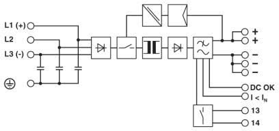
Application Diagrams
Schema a blocchi di alimentazione industriale QUINT-PS/3AC
Schema a blocchi di alimentazione industriale QUINT4-PS/3AC/24DC
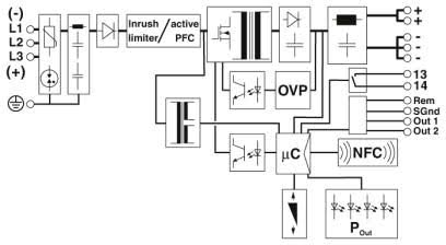
Diagramma schematico
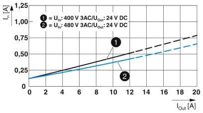
Corrente di ingresso e corrente di uscita QUINT4-PS/3AC/24DC/10
Corrente di ingresso e corrente di uscita QUINT4-PS/3AC/24DC/20
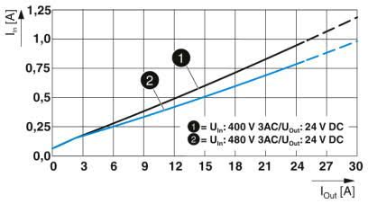
Diagramma del fattore di potenza QUINT4-PS/3AC/24DC/10
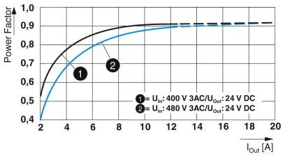
Diagramma del fattore di potenza QUINT4-PS/3AC/24DC/20
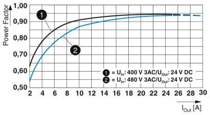
Diagramma di efficienza QUINT4-PS/3AC/24DC/10
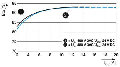
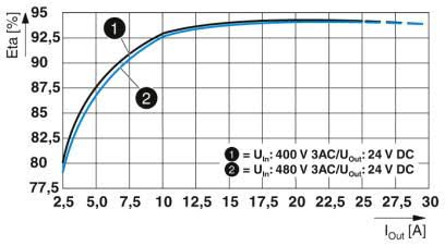
Diagramma di efficienza QUINT4-PS/3AC/24DC/20
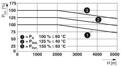
Potenza in uscita in base all'altezza di installazione QUINT4-PS/3AC/24DC/10
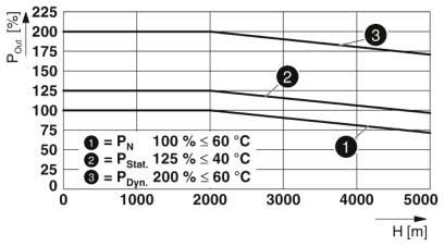
Potenza in uscita in base all'altezza di installazione QUINT4-PS/3AC/24DC/20
Fare clic sul numero di parte del prodotto per informazioni sull'ordine.
Immagine del prodotto
Descrizione
Numero parte
QUINT4-PS/3AC/24DC/10 Power Supply - QUINT power supply with free choice of output characteristic curve, SFB (selective fuse breaking) technology, and NFC interface, input: 3-phase, output: 24 V DC/10 A
QUINT4-PS/3AC/24DC/20 Power Supply - QUINT power supply with free choice of output characteristic curve, SFB (selective fuse breaking) technology, and NFC interface, input: 3-phase, output: 24 V DC/20 A
QUINT-PS/3AC/24DC/40 Power Supply - QUINT power supply for DIN rail mounting with SFB (Selective Fuse Breaking) Technology, input: 3-phase, output: 24 V DC/40 A
QUINT-PS/3AC/48DC/20 Power Supply - QUINT power supply for DIN rail mounting with SFB (Selective Fuse Breaking) Technology, input: 3-phase, output: 48 V DC/20 A
